
Rainscreen Vent Lab
Set the wind, the vents, the storey height and the cavity gap, and watch what the cavity's air does to the water at a Nichiha EX joint. The pressures and the water's height come from a physics model; the moving drops show the path.
- Pick a scenario or set the wind, the vents and the compartment.
- Watch the joint at the gust: drag the time bar to freeze any moment.
- Read the result and the sweeps. Tap i beside anything for what it means.
Gust cycle: one clean gust every period, easiest to read. Gusty wind: random gusts drawn from the von Kármán turbulence spectrum around a mean, closest to real weather. Steady: a held pressure, for the settled state.
Wind pressure on the panel face at the bottom vent's height, p = Cp·½ρV². A windward wall has Cp ≈ 0.8, so a 20 m/s gust gives about 190–240 Pa and a 29 m/s storm gust about 500 Pa. This is the pressure the vents have to let into the cavity. Thai code DPT 1311-50 (the rule for walls under the 2024 notification), 10 m windward wall: Bangkok 684 Pa ultimate, 513 Pa serviceability; the southern Gulf coast (zone 4A: Chumphon, Songkhla, Gulf-side Surat Thani and Nakhon Si Thammarat) 984 Pa. A Bangkok 2-year storm is about 240 Pa, the Lab's default.
The wall pressure in the calm between gusts. The cavity sits at about this pressure before each gust arrives.
How fast the gust builds. The cavity can only follow by drawing air in through the vents, so a fast rise leaves it behind for a moment and the joints feel the gap. Field records rise at about 4,000 Pa/s (Place Air Canada, NRC); the EN 12865 lab pulse takes 3 s, far gentler.
One row of holes or slots in Nichiha's aluminium profile; untick a vent to block it.
Open area of a vent per metre of wall, mm²/m: the area of its openings along one metre. LGS's J-flashing is an aluminium profile; what LGS can change is its machining: one row (the profile has no room for two) of 6 × 14 mm slots or 6 mm round holes, at a spacing centre to centre. LGS's flashing has 6 × 14 mm slots 45 mm apart (measured by LGS): 1,695 mm²/m per row. The model treats each opening as a sharp-edged orifice, Q = Cd·A·√(2Δp/ρ) with Cd 0.61. The closest centres leave one hole width of metal: 20 mm for slots, 12 mm for holes.
The starter at the foot of the compartment, on the story-break flashing below: where the cavity breathes in and drains. Untick it to model it blocked (mortar, sealant, debris).
The vented J-channel under the next story-break flashing: the compartment's top vent. LGS's vented J-flashing: the cavity air rises behind its back flange, through a row of slots in the back plate, across the U-channel, through a second row in the cap's inner wall and out of the 7 mm outlet. The engine takes that path as one orifice, 1/A² = 2/A_row² + 1/A_outlet²: about 70 % of one row (1,181 mm²/m with 6 × 14 mm slots at 45 mm). Untick it to model it blocked (sealant, paint, insects, debris).
How much the wall behind the cavity gives. When the cavity pressure rises, the 9 mm Glasroc X bows in between studs at 600 mm and the cavity grows, so the vents must supply that volume too; it is most of what they fill. Rigid wall: no give. LGS, lining sealed: the stud bay's air and the lining behind resist the bowing. LGS, stud bay open: the bay breathes to the room and the board bows freely (the slowest cavity).
Distance from the bottom vent to the top vent: the height between story breaks. A taller compartment holds more air per metre for the same vents to fill, and its two vents see more different wind pressures, so its top and bottom joints are pushed harder.
Clear depth of the air space between the back of the panel and the Glasroc X. It sets the air volume and the friction up the cavity (laminar flow between plates, Δp = 12μUL/d²): a narrow gap barely ventilates. Under about 5 mm, drops can bridge to the Glasroc X.
The factory seal strip on the tongue (a 2.4 mm round PVC strip, squeezed 33 % into the 1.6 mm slot). Where it is seated it holds far more than any wind: a finite element model of the strip glued on the tongue and pressed by the lip (FEBio, 29-09-2026) gives 2.4 to 6.5 MPa of contact stress for solid PVC of Shore A 60 to 80, and still 1.5 MPa or more after heavy compression set; a foam strip would hold 14 to 24 kPa. The CFD agrees: with the strip pressed, the water stops at it at 300, 1000 and 3720 Pa. Joints leak where it is not continuous: at the clips, panel ends, four-way junctions and cut ends, and where a panel is not pushed home (only 0.8 mm of squeeze, and heat and age take a quarter to half of it). Japanese tests of six clip-fixed sidings (NILIM report 975, 2017) found water through the joints from about 150 Pa, near the lap's own water head, and Nichiha relies on the ventilated cavity, not the strip. Gap in the strip models those places: only the 15 mm lap holds the water.
How readily water wets the panel edges: 0° spreads flat, 90° beads up. In a narrow gap the meniscus pulls water up with p = 2σ·cosθ/w, so a lower angle helps water over the lap. Nichiha publishes none for its edges; ordinary coats sit near 80°, hydrophilic ones at 40° or less.
Which course joint the section shows. Joints come every 455 mm up the compartment; the worst is the one with the highest peak push.
More inputs: leaks, rain, board stiffness
On a windward wall the pressure grows with height, as the wind speeds up away from the ground. The two vents then see different pressures and the cavity settles between them, so the top and bottom joints feel the difference. 4 %/m is an estimate for low-rise walls, and it is the input that most limits a tall compartment.
Air paths through the cladding itself (butt joints, cut ends, trims), as orifice area per m² of wall. With the vents closed they are the only way the cavity can follow the wind.
Air lost from the cavity through the Glasroc X and the lining to the room, rated at 75 Pa, Q = C·Δp^0.65. It keeps the cavity from ever quite matching the outside. 0.2 L/(s·m²) is the air-barrier assembly limit (ASTM E2357).
Rain rate. It sets how much water reaches each joint (ISO 15927-3 form), so it changes the water that gets over the tongue, not the pressures. Thai 15-minute rain (Yamoat et al. 2022): 50-year 214 mm/h Central, 206 mm/h South; 2-year about 70 mm/h Central.
Sun heats the cavity air and it rises: the stack effect, Δp = ρgH·ΔT/T. It ventilates (dries) the cavity when there is no wind.
Discharge coefficient of the vent openings: 0.61 for a sharp-edged hole in thin sheet; lower for a grille or insect mesh.
Bending stiffness of the sheathing and lining, for their bowing between studs. Not published; plasterboard measures 1.7–2.3 GPa in-plane. Softer boards make the vents work harder.
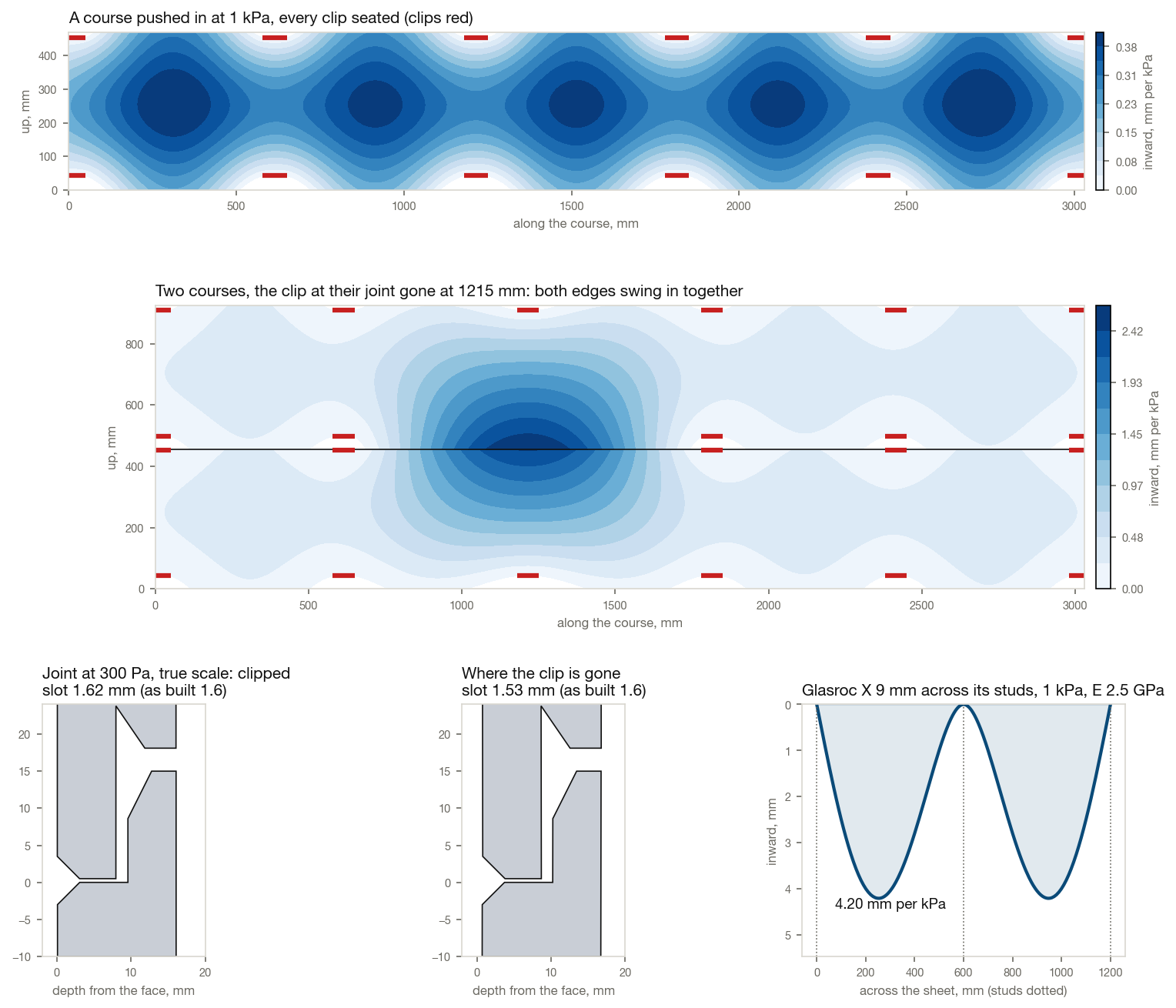
Bending stiffness of the panels, for their bowing between clips. Each 470 mm course is held only by the clips at its two joints, so it bows both ways: 0.26 mm on average per kPa at 5 GPa (CalculiX shell model). The panels act as a piston that squeezes the cavity when the wind pushes them, which helps a little. Not published for EX.
01 · The joint in section
True scale: the tongue stands 15 mm above the shoulder, the slot is 1.6 mm wide. Colours are air pressure on one legend for the whole run, so a colour means the same pressure in every frame: the same colour either side of the joint means the cavity is keeping up. The strip on the left is the whole compartment, heights to scale, depths not; tap a joint to show it. Drops and pathlines move 12 times slower than life. In the cavity the pathlines move at the air speed the model computes; outside, the wind's turn and its eddies, and the dip the eddies put in the pressure, are illustrative. The water's film down the face follows the CFD runs, and so does the joint without its seal strip: air forces in from about 200 Pa; above about 275 Pa the bubble grows and, 0.14 to 0.17 s later, blows the water out and throws it across the cavity at the runs' speed; the joint stays open until the push falls. Wetter edges hold longer, drier ones blow sooner. The shapes are illustrative. Axes in millimetres; triad: X into the wall, Y up.
See the water in the joint solved by CFD, frame by frame ↓
02 · Pressure through the gusts
Joint
03 · What each setting buys
Each point is a full run with everything else as you set it; the blue dot is where you are. Drying is the sun warming the cavity 5 K with no wind: air rising through the vents.
04 · Result
| Joint | Up (m) | Push (Pa) | Water (mm) | Status |
|---|
05 · The water, solved by CFD
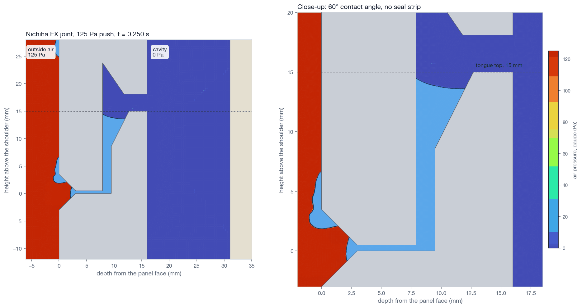
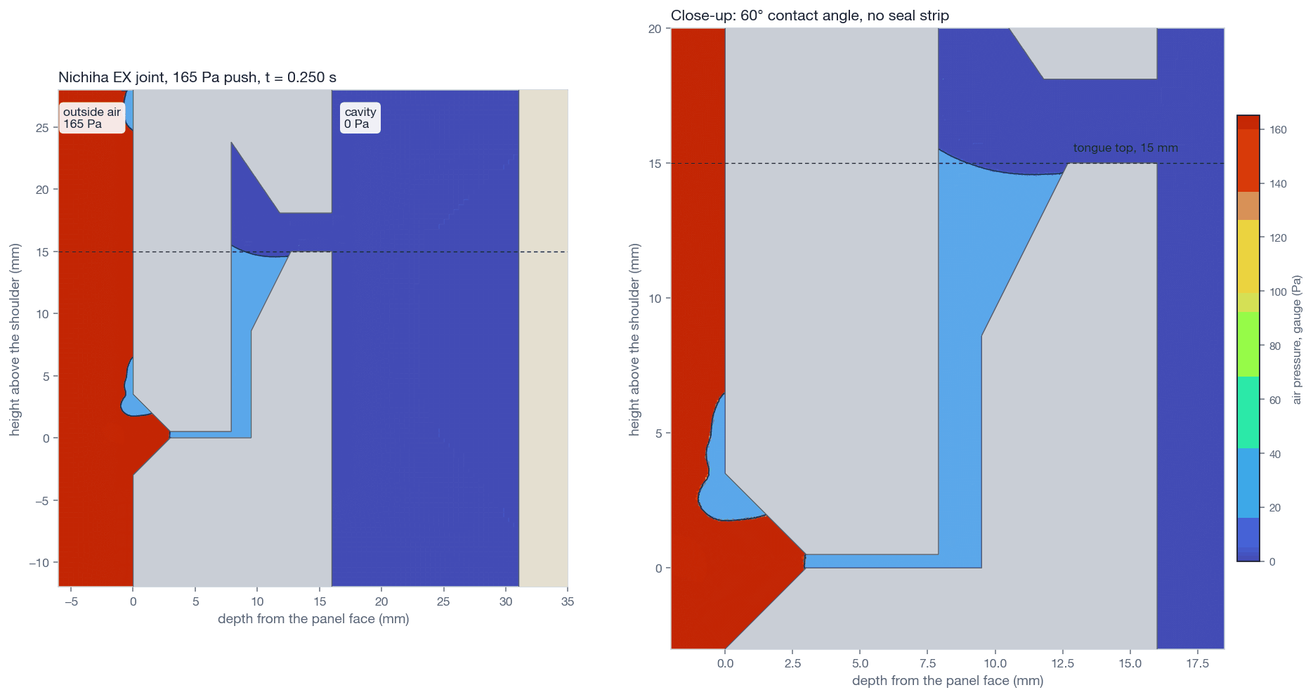
Modelled, not testedOpenFOAM interFoam (volume of fluid, a free-surface method) on the true EX joint, 60° contact angle, without and with the seal strip: the air coloured by the pressure it solved, the water blue. Each frame is the solver's own result, not a drawing. The contact angle on these edges is not published: at 75° the joint blew at 250 Pa (0.138 s); at 45° it held 250 Pa for the full 0.3 s and 290 Pa until 0.297 s. The other runs use 60°.
165 Pa across the joint, 33 Pa over the 132 Pa the Lab's simple model gives. The water climbs the slot to the tongue's top and stops at its sharp corner for the whole 0.25 s: the corner pins the water surface. A chipped or dirty corner loses that, so the Lab keeps 132 Pa.
The wind moves the boards too: CalculiX with the CFD
The gust that pushes water up the joint also bows the boards. CalculiX shell models of a course on its clips and of the Glasroc X on its studs give the movement, and the CFD ran the joint as the wind shapes it. One JE825 clip holds both courses at a joint, so they move together: at 300 Pa the slot opens 0.02 mm, and even with a clip gone it closes only 0.05 mm (0.13 mm at a panel's end). Between studs the Glasroc X bows in about 1.7 mm per kPa of cavity pressure; the section above cuts there and shows it. None of this moves the moment water gets through by more than 0.005 s, no more than a finer mesh moved it: the joint keeps its shape in the wind.
| The joint in the wind | Slot at 300 Pa | Water through, 280 Pa | 300 Pa |
|---|---|---|---|
| As drawn, not moving | 1.60 mm | 0.168 s | 0.140 s |
| Clipped | 1.62 mm | 0.166 s | 0.139 s |
| A clip gone, mid-panel | 1.55 mm | 0.173 s | 0.144 s |
| A clip gone, panel end | 1.47 mm | 0.164 s | 0.143 s |
| Clipped, cavity 0.9 mm deeper (Glasroc X bowed in) | 1.62 mm | not run | 0.139 s |
06 · How to read this
The joint is a manometer; the cavity is a tank
Two tests
- The lap alone, 132 Pa: where the seal strip is missing, the water reaches the top of the tongue at 132 Pa, and a chipped or dirty corner lets it into the cavity. A clean, sharp corner held it in the CFD until the air blew it out at 280 Pa (270 Pa held for 0.3 s). The contact angle is not published: at 45° the joint held 250 Pa for 0.3 s and 290 Pa until 0.297 s; at 75° it blew at 250 Pa. The Lab uses 60°. 132 Pa is the safe line for leaks.
- With the seal strip in place and pressed on the lip, water stops at the strip (OpenFOAM, 240 Pa).
Taken as given (estimates)
- Bending moduli: Glasroc X and lining 2.0 GPa, Nichiha 5.0 GPa. Neither maker publishes one. The boards bend as plates; each 470 mm course is held only by the clips at its two joints, so it bows both ways, 0.26 mm on average per kPa (CalculiX shell model).
- The joint keeps its shape. The wind bows the panels, but one clip holds both courses at a joint, so they move together: the slot opens 0.02 mm at 300 Pa, and even with a clip gone it closes only 0.05 mm (0.13 mm at a panel's end). The CFD with the joint moved so gives the same moment of blow-through within 0.005 s (section 05). Between studs the Glasroc X bows in about 1.7 mm per kPa of cavity pressure, the lining sealed behind it; the section shows it.
- Glasroc X 9 mm (LGS, 28-09-2026); the datasheets found list 12.5 mm only.
- Contact angle 60°; wind pressure rising 4 % per metre up the wall; cladding leaks 20 mm² per m².
- Vent openings as sharp-edged orifices, Cd 0.61; the joints themselves airtight (seal strips and water close them).
- The LGS J-flashing's slots: 6 × 14 mm, 45 mm apart (measured by LGS).
- Joint as built, strip in place: tests of six clip-fixed Japanese sidings (NILIM report 975, 2017) found water through the joints from about 150 Pa where the strip was not continuous; the Lab takes that for the LGS joint, with 5 mm² of gap per metre (NILIM's 1–5, leakier end).
Words used here
- Rainscreen
- Cladding with a drained, vented cavity behind it, so rain stops at the cladding and the wall behind stays dry.
- Pressure equalisation
- Letting the cavity follow the wind's pressure through vents, so the cladding's joints feel little push.
- Compartment, story break
- The stretch of cavity between two horizontal closures (story-break flashings); it fills and empties as one.
- Starter, vented J-channel
- The profiles at the foot and head of a compartment: the cavity breathes in at the starter and out through the J-channel's slots.
- Lap, tongue, lip, slot, V, hairline
- The shiplap edge: the lower panel's 15 mm tongue stands behind the upper panel's lip; the 1.6 mm slot between them, the V at the face and the hairline under the lip are the water's way in.
- Seal strip
- The factory 2.4 mm round PVC strip on the tongue, squeezed into the slot.
- Contact angle
- The angle a water surface meets a solid at; a low angle wets and wicks.
- Field gust
- A gust as measured on a real building, rising at about 4,000 Pa/s: far faster than a lab test's 3 s pulse.
Sources
- NRC CTU-34: vent and drain holes at least 10 mm wide against bridging water.
- Garden, CBD-40 (NRC 1963); Killip and Cheetham, Building and Environment 19(2) 1984; Baskaran, NRC IR-629 (1992).
- Field gusts at about 4,000 Pa/s: Ganguli and Dalgliesh, J. Struct. Eng. 114(3) 1988.
- NILIM report 975 (2017), ch. V: six clip-fixed Japanese sidings; water through the joints from about 150 Pa; fitted gaps 1–5 mm² per metre.
- Thai wind code DPT 1311-50 (2007), required for walls by the Ministry of Interior notification of 30-08-2024; rain: Yamoat et al. (2022), Thai intensity-duration-frequency statistics.
- Nichiha モエン standard installation guide 2026: cavity at least 12 mm, 10–15 mm open at the base flashing. Nichiha USA AWP Horizontal guide (09-2025) p. 14: metal framing of three storeys or more, a compression joint every other floor.
Check by CFD: water in the joint, OpenFOAM
OpenFOAM interFoam (volume of fluid) on the true EX joint: 39,823 cells, 0.075 mm in the joint, 60° contact angle, no seal strip, the slot prefilled to 13 mm, 0.25 s per push. Water height at the end, CFD against the Lab's engine: 115 Pa 13.8 mm (engine 13.6), 125 Pa 14.4 mm (14.4), 135 Pa 15.0 mm and still rising (engine: over the top). At 145 and 165 Pa the water reached the tongue's top and stopped at its sharp corner; none crossed into the cavity in the run. A clean, sharp corner pins the water surface and holds more than the 132 Pa the Lab's simple model gives, at least 165 Pa for 0.12 s here. A chipped, rounded or dirty corner loses that, and real gusts last longer, so the Lab keeps 132 Pa.
Modelled by LGS engineering: a physics model checked against closed-form solutions and CFD, and this page's engine checked against it case by case. Not a product test: every figure comes from a model and still needs an engineer's sign-off.
Want these numbers for your own house? Tell us about it.